
Curing Systems
Non Contact Infrared Temperature Sensors in Curing Systems in textile drying
When using infrared temperature sensors (IRt/c) in curing systems there are three common challenges that you should consider:
- During the curing process, the intense heat from the curing lamps conducted to the sensor area can cause the sensor to exceed its specified body temperature limit of 100°C (212°F), which, in turn, can cause the sensor to fail.
- When power to the entire machine is shut off after it has been operating normally for some period, residual heat from the curing lamps and associated components is hot enough to cause the sensor to exceed its body temperature limit.
- When curing lamps are positioned closely together, they may restrict the sensor’s view of the target and may increase the probability of the sensor signal being influenced by a partial view of the hot lamps. The result is an excessively high temperature indication for a few seconds when the lamps are off and no target is in the view.
In order to achieve optimal ROI and operational efficiency in processes that require curing systems, it is ideal to employ a cost-effective IRt/c sensing system. These systems require no calibration, no operator attention, can withstand abuse in the field, and can be easily replaced if needed. Following are solutions to the three most common challenges that occur when employing an IRt/c sensor in a curing system.
Solution to Problem 1: Sensor overheating during operation
Sensors needs a constant flow of forced air (ambient air) guided along and around them for several reasons. First, the air helps ensure that the sensors remain close to the ambient temperature during operation. Secondly, if a small portion of the air is guided toward the sensing element, sufficient pressure is created to prevent dust from entering the sensor unit and landing on the sensing head, which can disturb the reading. An easy way to suply the air required for this purpose is to employ the fans that cool the whole system. When doing so, it is important to be sure that the guided air leaving the sensor does not blow on the fabric, creating a cool spot. (A good solution to this challenge is to mechanically guide the air -- after cooling the sensor body -- at a 90° angle away from the sensor). In order to determine if there is sufficient airflow to cool the sensor, we recommend employing an additional contact temperature sensor connected to the body of an IRt/c. If the contact sensor detects that the body temperature of the IRt/c is increasing, it is likely that the curing system’s air filters are getting clogged and need cleaning.
Clogged filters reduce the air flow used for cooling, and the increase in temperature can be directly measured at the IR sensor’s body. The contact sensor embedded in the IR sensor provides an ideal tool with which to assess air filter conditions. This approach provides a simple and reliable method to prevent damage to both the sensor and other electrical components that can be caused by clogged air filters. Exergen can provide this configuration as a special build.
Solution to Problem 2: Sensor overheating after power shut down
While fans will normally help prevent overheating after the curing sytems has been shut down, if a power outage occurs (as often happens in countries like Mexico, Bangladesh and others), the sytem is at risk.
Exergen recommends the following solutions to avoid overheating during power outages:
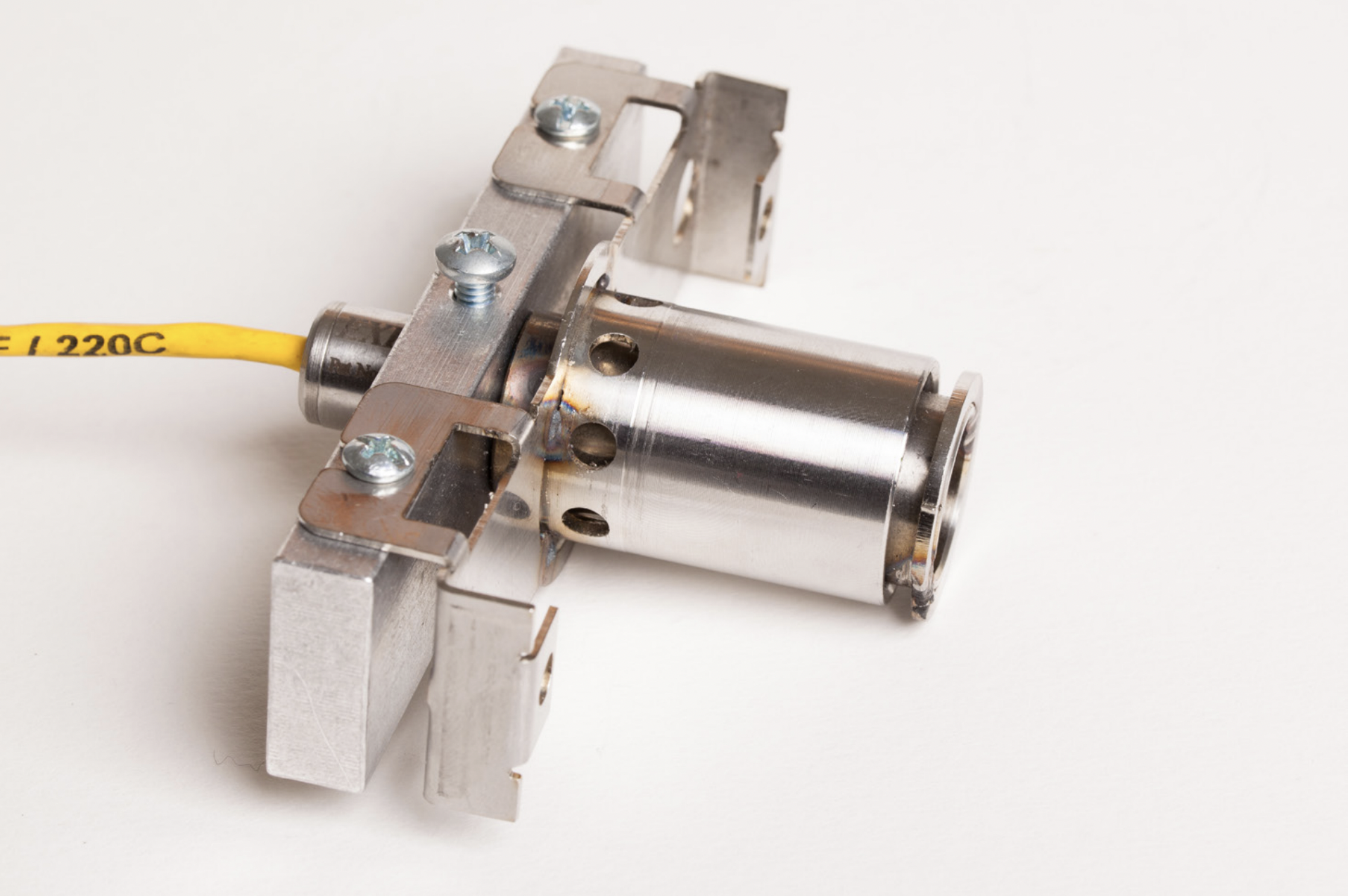
- A simple heat sink can be clamped to the sensor to absorb the conducted energy and help avoid raising the sensor temperature.
- The heat sink should be made of aluminum. Since alumuminum is 12 times more thermally conductive than stainless steel and has more than twice the specific heat of stainless steel, it absorbs heat quickly and uniformly.
- The heat sink should weigh > 226,7 g (8 oz) or so (>10 times the weight of the sensor), in order to reduce sensor temperature increases by a ratio of more than 20 to 1. For example, if the sensor temperature rose to 50°C (122°F) at shutdown, the heat sink would reduce that increase by about 1,9 °C (3°F) or 3,8°C (6°F).
- The heat sink can take the form of an “L” shaped bracket centered in the air flow path with the sensor mounted at one end and the bracket thermally insulated from the reflector plate. The air flow will keep the heat sink at about 70°C (158°F) during normal operation. At shut down, the heat sink and sensor temperature will rise only a few degrees, thus protecting the sensor in a simple reliable manner.
Since there is effective and reliable cooling available at no cost via the cooling fans as described above, there is no benefit to deploying sensors that operate in temperatures of up to 180°C (356°F) uncooled. Such sensors add about > $ 200 to the system cost when compared to standard 50°C (212°F) sensors.
.png)