
#89: IRt/c specifications: real world performance accuracy
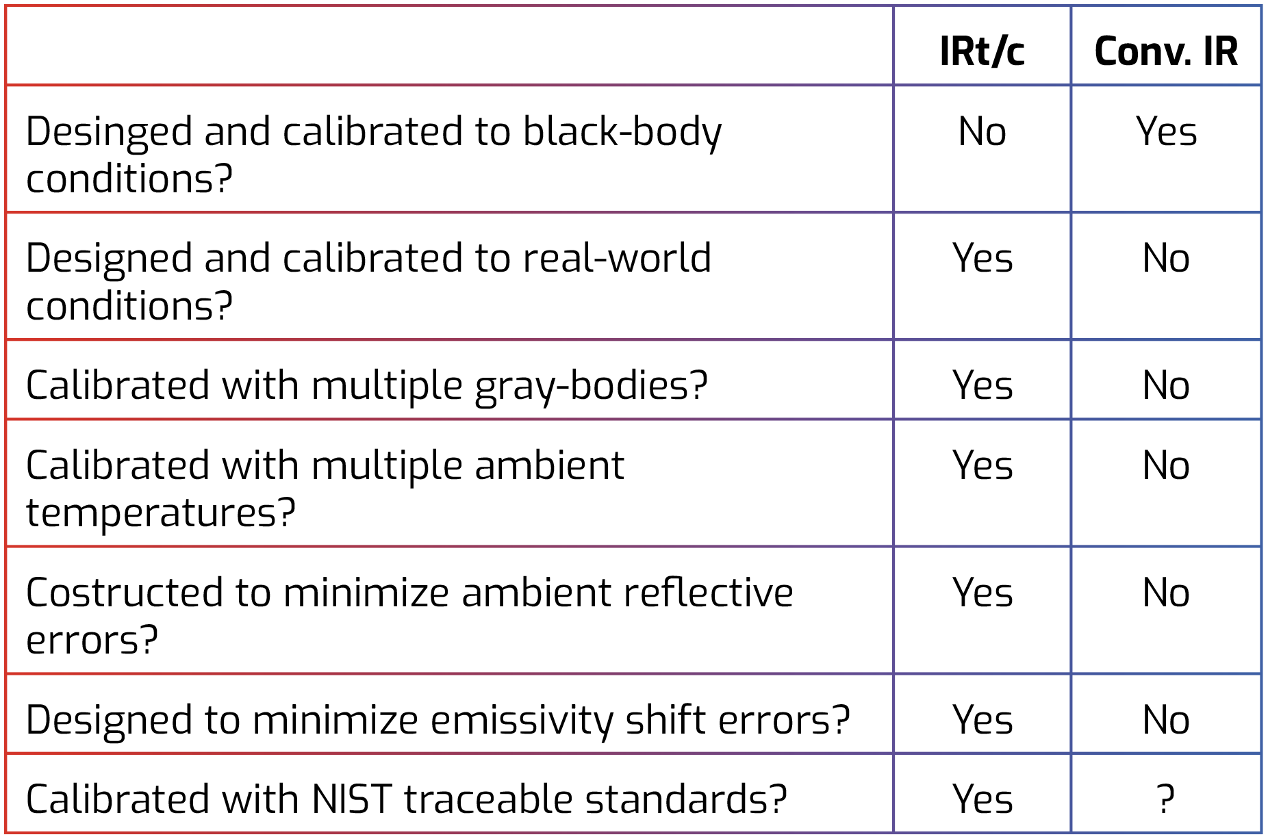
The table below summarizes some of the major differences between how IRt/c’s are designed and calibrated, compared to conventional infrared devices, with the objective of providing the best possible accuracy under actual real-world conditions.
Why the IRt/c is Different
The concept of a black-body is a highly useful and essential mathematical construction in the application of infrared radiation physics, and has had firm theoretical support from the time of Max Planck nearly 100 years ago. However, in the real world application of infrared methods for temperature control, IR devices do not measure black-bodies.
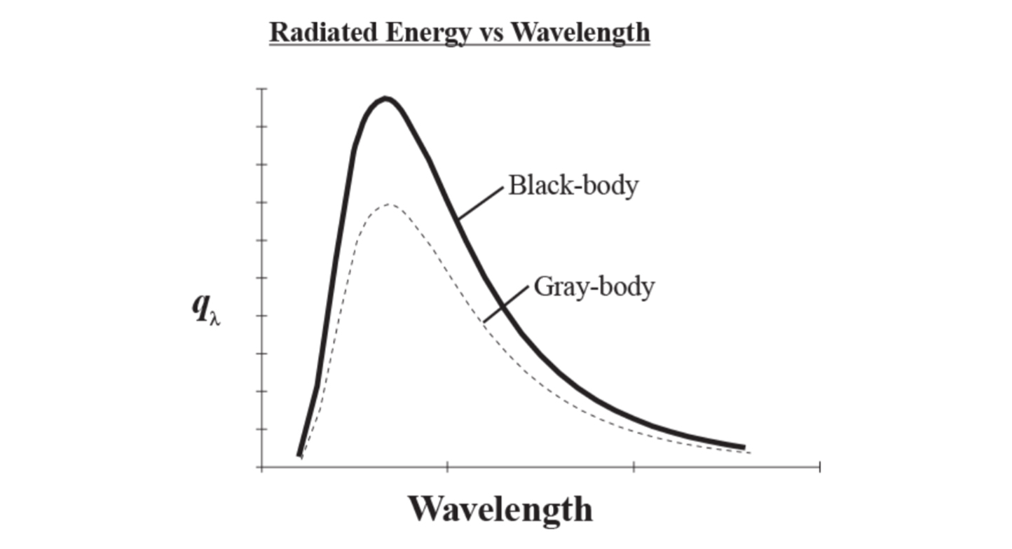
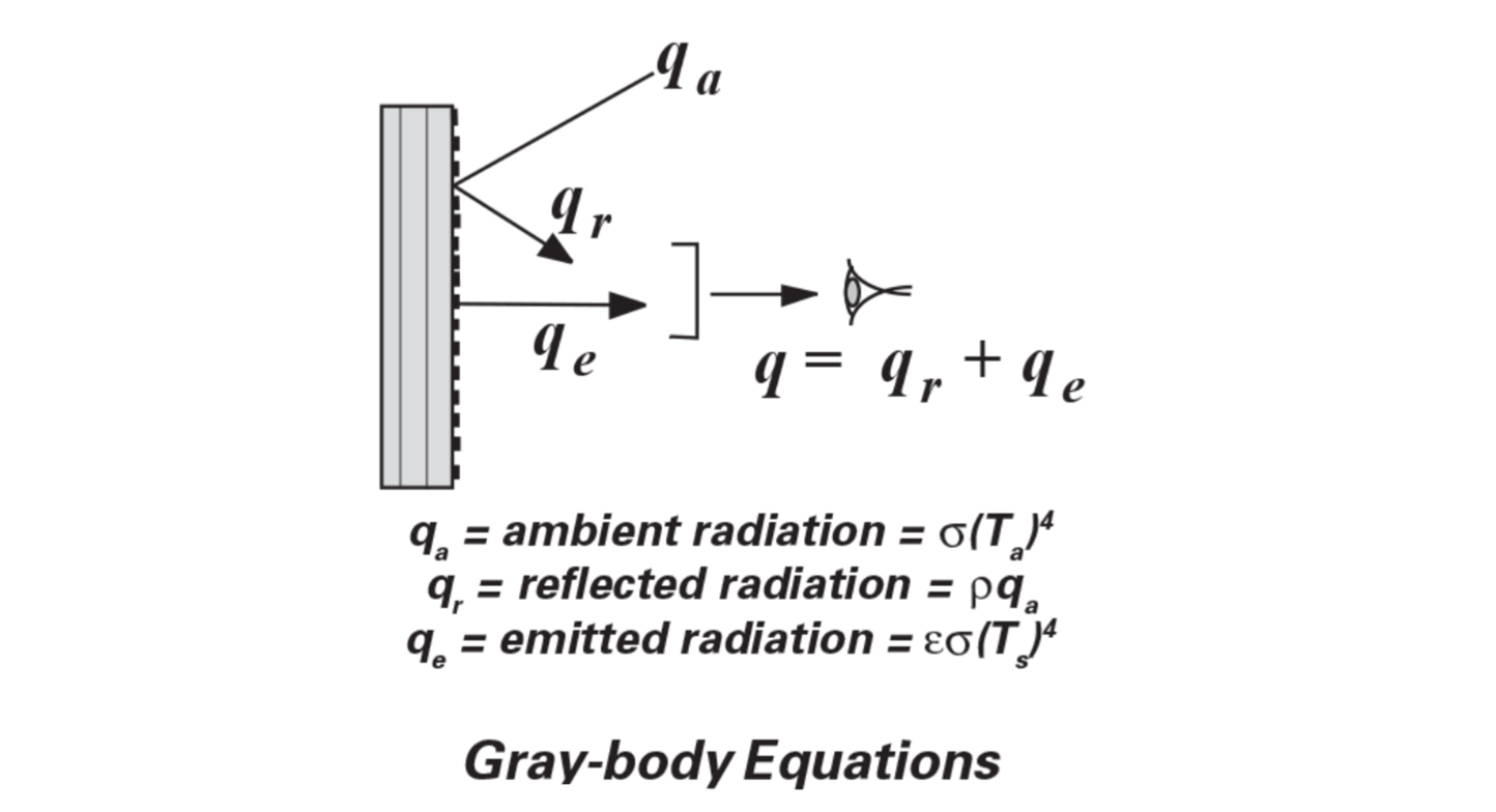
More realistically, real-world measurements are performed on targets that approximate what is termed a gray-body, i.e. materials which have an emissivity less than 1. Gray-bodies also have the further characteristic that emissivity is constant at ll wavelengths of interest. Then for gray bodies:
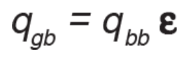
at all wavelengths, where qgb and qbb are radiated energy from a gray-body and black-body respectively.
An important element which is missing when working with black-bodies, but present with graybodies is reflected radiation. For nontransparent materials, emissivity plus reflectivity always equals one:
Accordingly, for a black-body = 1, and therefore = 0. But for a gray-body < 1 and therefore > 0, and the reflected radiation due to ambient temperature must be considered. Refer to Tech Note #64 for further details.
IRt/c’s are specifically designed to be accurate and reproducible under real world conditions of targets that approximate gray-bodies, with ambient temperatures that vary, thus with reflected radiation that varies. The performance specifications of the IRt/c, unlike conventional infrared devices, include graybody effects.
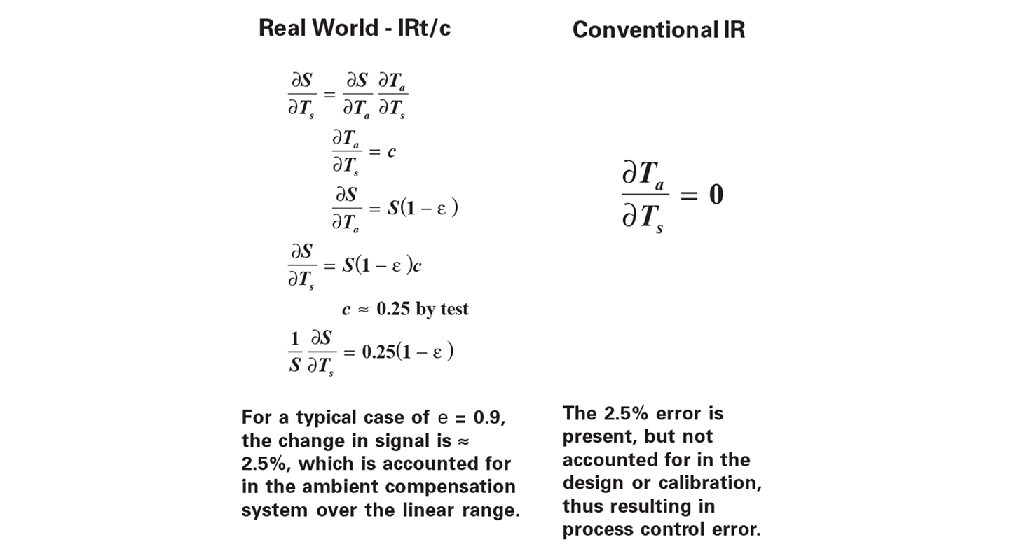
Mathematically the signal output of an IRt/c is a complex function of target temperature, ambient temperature, target emissivity, reflected energy, thermocouple type, etc. To clarify the specifications we can represent the change in signal with respect to a variable of interest, while holding all other variables constant, as a partial derivative.
Ambient Temperature Coefficient Specification
The variation in output signal with ambient temperature, which is the Ambient Temperature Coefficient specification, can be represented as below:
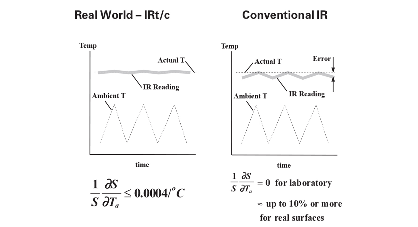
where S is the output signal and Ta is the ambient temperature. This equation describes the output of the IRt/c, including a gray-body assumption of emissivity = 0.9, and that the sensor itself is at the same temperature as the environment.
What this means in practice is that when an IRt/c is installed and calibrated in place (Tech Notes #1, #64), the IRt/c body tends to change temperature with the ambient background that the target sees, then internally applies the correction required to reduce errors. Without this feature this error could be many times higher, and cause unwanted shifts in process control temperature.
For example, waterless printing processes require that the ink application roll to be temperature controlled in order to maintain high quality. If the temperature is to be controlled at 26,7°C (80°F), and the press enclosure
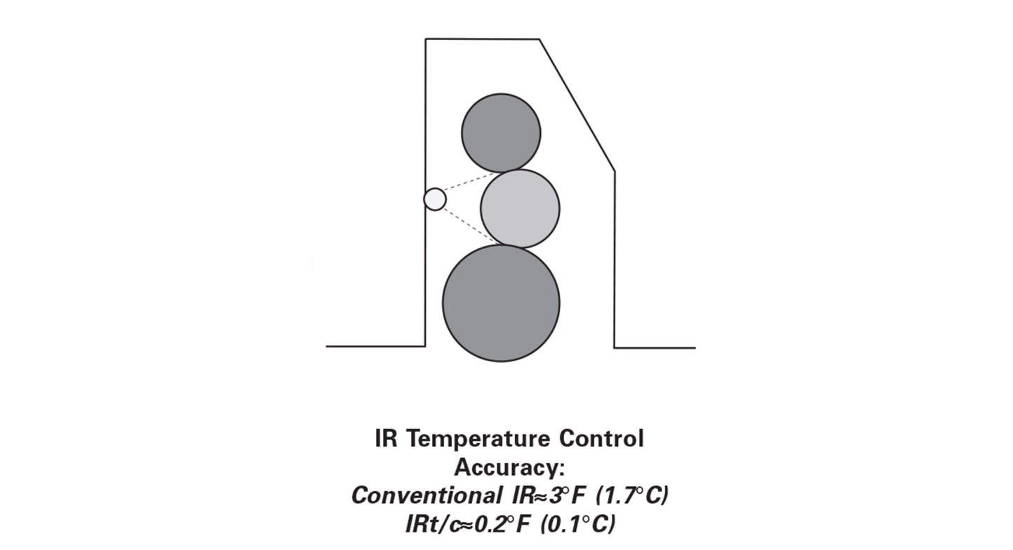
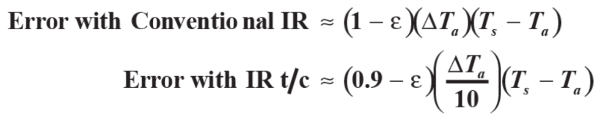
can vary over the range 21,1 to 37,8°C (70 to 100°F) due to warm-up, weather, air ventilation, etc.; then a conventional IR device will produce an error of about 1,7°C (3°F), while an IRt/c will produce an error of only 0,1°C (0.2°F). Thus, the IRt/c provides ten times more accurate control than the conventional device. To estimate the improvement in control accuracy produced by the IRt/c for a specific application, the following approximation can be applied:
Compensating for Emissivity Variations
A common assumption for conventional IR thermometry is that emissivity is constant with changes in target surface temperature. Real materials do not have this characteristic. The average value for nonmetals for which the change in emissivity with respect to surface temperature has been reported, is approximately - 3% per 100°C target temperature change (- 2% per 100°F). Note: Thermal Radiative Transfer and Properties, MQ Brewster ed., John Wiley & Sons, 1992.
Applying the partial derivative mathematical formulation, the emissivity variation is:
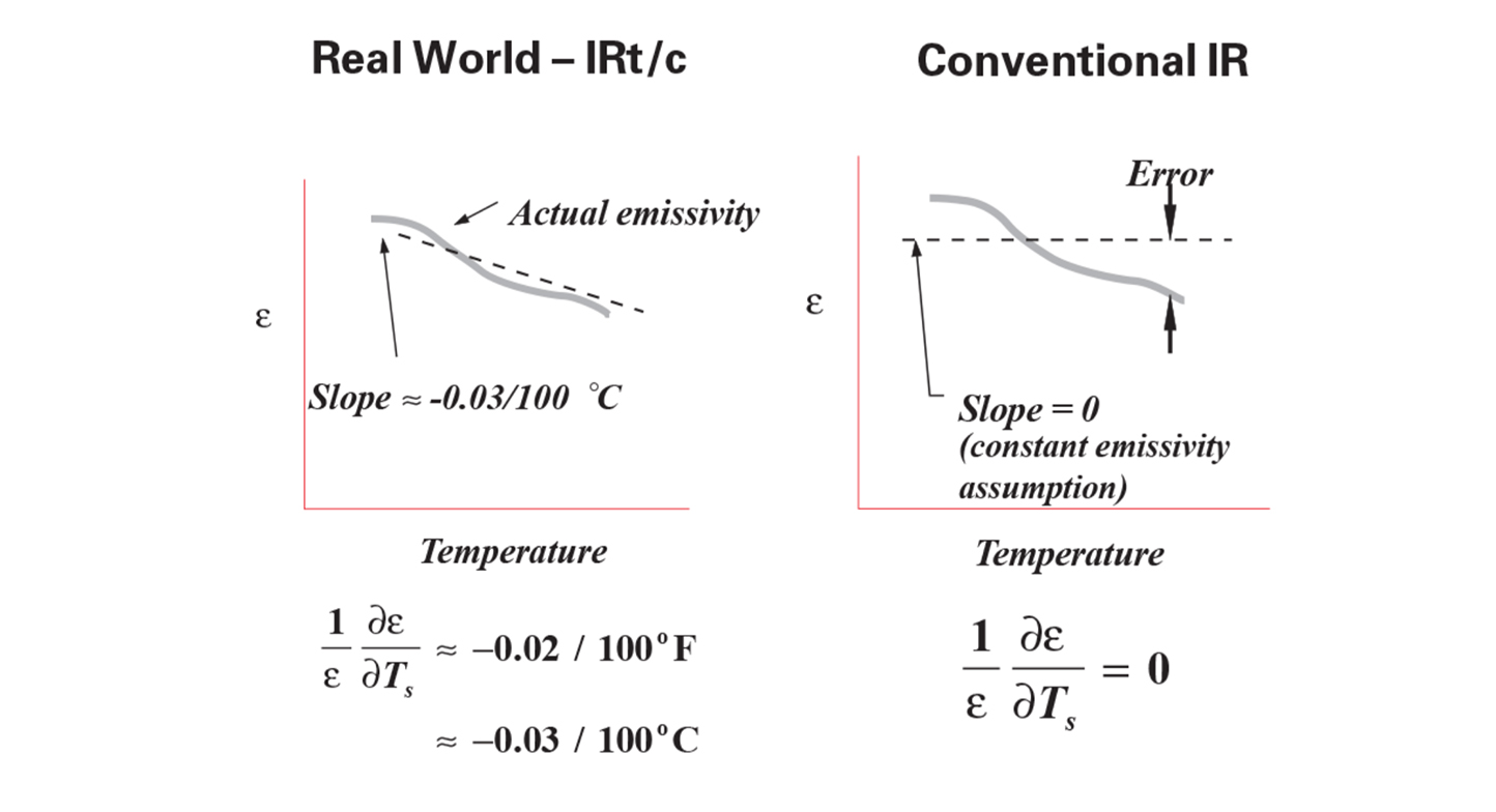
Conventional IR misses this effect, and will cause process control errors.
The signal produced by the IR device is proportional to the radiation emitted by the surface:
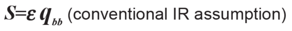
then the change in signal with respect to target surface temperature may be presented as follows:
Note that the conventional IR device loses one term of the signal change with respect to surface temperature. When the IR signal is converted to a temperature indication, the signal in the conventional device is linearized, whereas in the IRt/c the signal is unchanged.
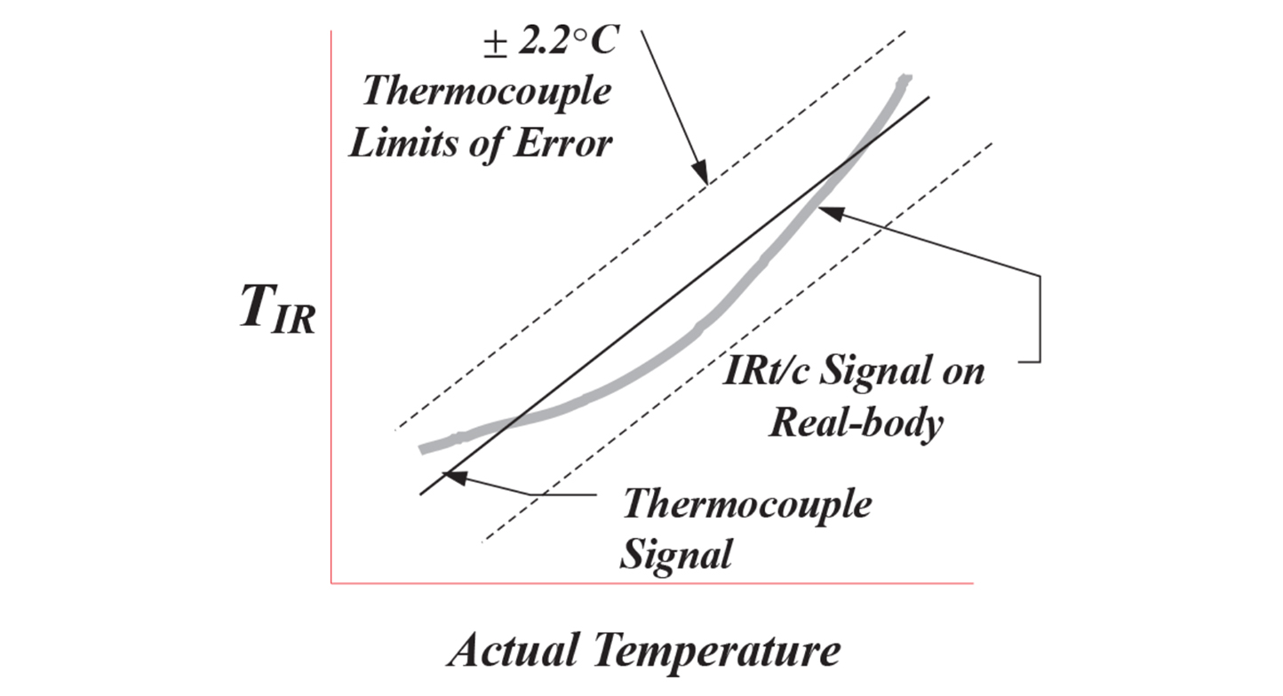
Since real-world emissivity for most non-metal materials decreases with temperature, the constant emissivity assumption of conventional IR devices produces errors in readings that are not obvious to the typical IR user and can be highly misleading over a wide temperature range. The IRt/c, however, is specified for a useable specific temperature range, where the effect of emissivity change is accounted for in the linearity specification, and the user is confident that his process control will be accurate. Note that testing an IRt/c with a black body will not give the same linear range as a realbody.
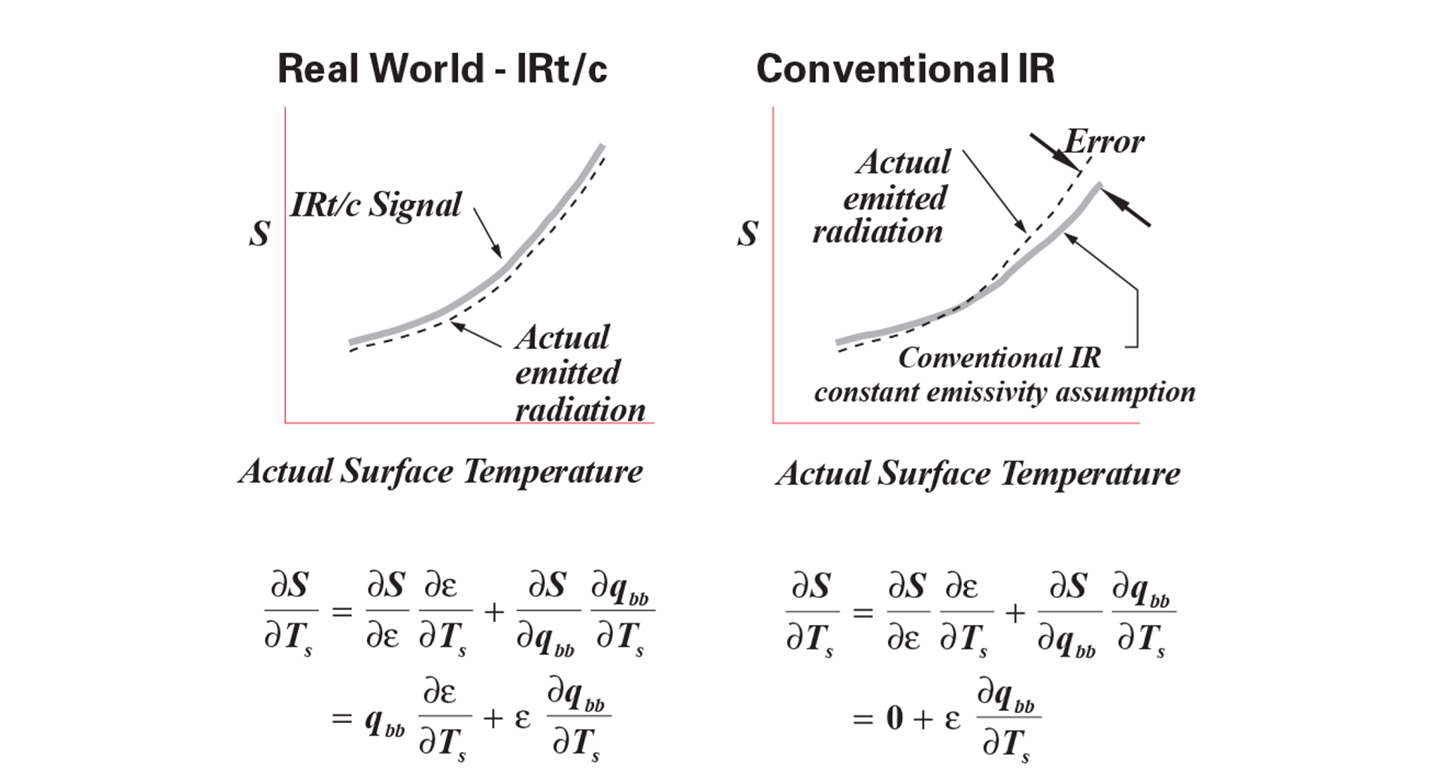
A second effect on linear range is the effect of target surface temperature on ambient temperature, and therefore the reflected component of radiation to the sensor. As target temperature increases within a process, the increased radiation heat transfer to the surroundings will cause the target ambient radiant background to also increase in temperature.
For example, a laminating process that has several temperature control settings that depend on the material and feed speeds, may operate with target temperatures that are 56°C (100°F) different. As the material changes temperature, the background radiation in the vicinity of the measurement will also change temperature, and influence the IR reading.
Accordingly, the variation in signal with target temperature has the additional component as follows:
Comparison to Standard Thermocouples
Standard thermocouples are generally specified as adhering to ASTM and ANSI specifications, hichprescribe a basic accuracy of ±2,2°C (±3.5°F), or 0,75% of reading, whichever is higher 2. Likewise, IRt/c’s are aalso specified to be within the same ±2,2°C (±3.5°F) limits, or to the percentages stated in their specifications, whichever is higher.
However, it is important to note that when an IRt/c is calibrated to installation, this error disappears.
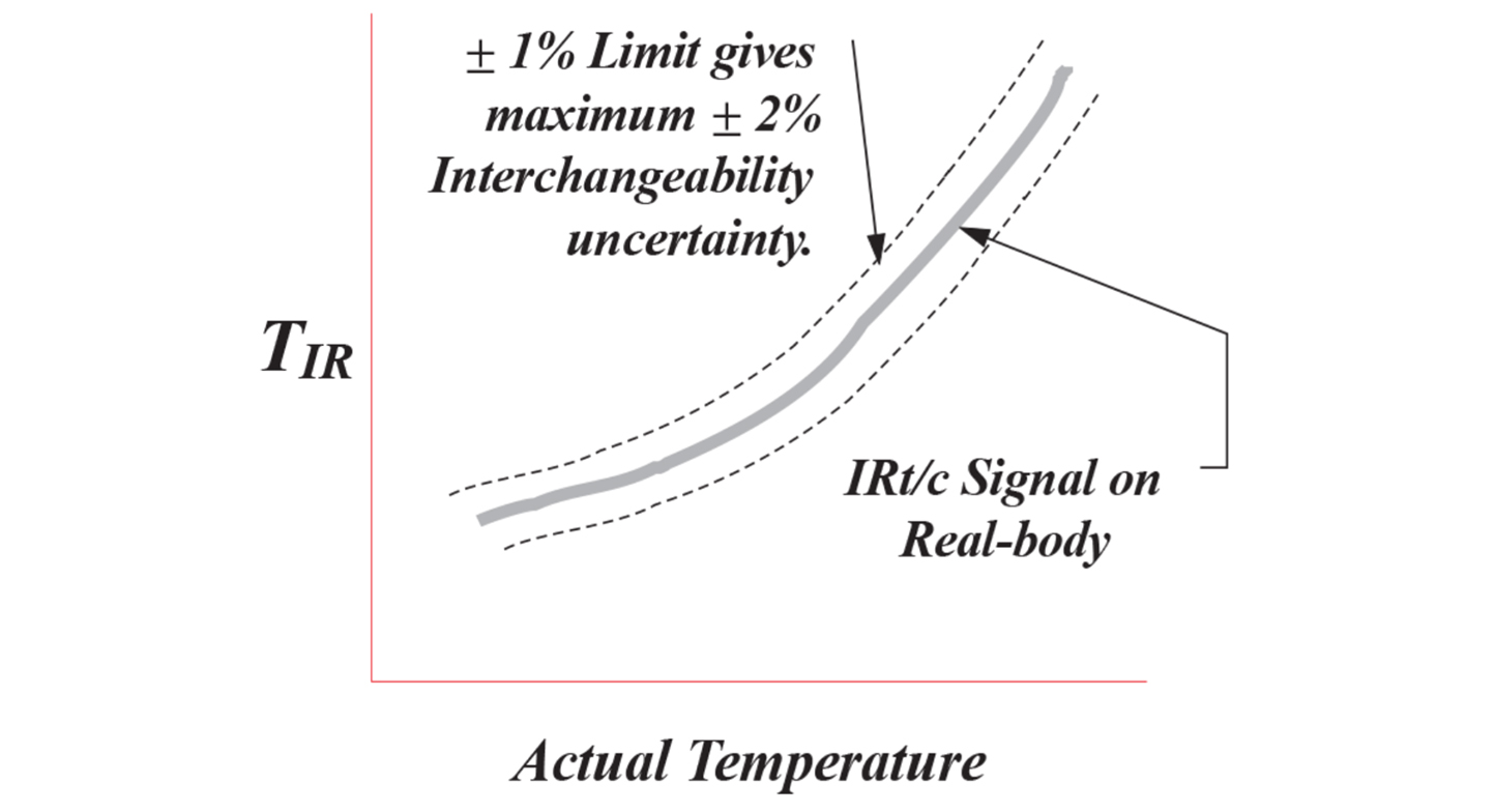
Repeatability and Interchangeability
The cardinal requirement for the IRt/c, as in any measuring device, is to repeat its calibration. The repeatability of IRt/c’s is specified at <0,1°C (<0.2°F).
Interchangeability uncertainty from one device to another is 2% maximum, since each individual device is built and tested to conform to standards with a ±1% tolerance, so is therefore able to produce a maximum of ±2% difference between any two devices. Typical interchangeability uncertainty, determined by test, is described statistically with standard deviation of approximately 0,5°C (0.8°F).
Summary
- The IRt/c is a different type of device compared to conventional IR, since it is carefully designed and built to produce real world accuracy for temperature control, with some subtle features that make a significant improvement over conventional IR.
- In-place calibration is always recommended, as it always is with any IR device due to uncertainties in emissivities and ambient temperature.
- For OEM applications, or multiple same-use applications in a factory, once the initial system has been qualified and calibrated, IRt/c’s of the same model can be substituted without the necessity of recalibration.
- An added benefit of the IRt/c is its specified useable linear range per model. (A user is not led into believing that his measurement is accurate over a wide temperature range, a common misunderstanding with conventional IR. Thermal physics and scientific data demonstrate that trying to track real-world surface temperatures over a range greater than approximately 56°C (100°F) involves accounting for increasing errors that cannot be handled by conventional IR devices. This includes not only permanently mounted IR sensors, but portable handheld IR devices, also.) There is one exception to this rule, however, the Microscanner D-Series portable IR scanners. (See Tech Note #33, #91) They have the largest useable target temperature ranges with the least amount of possible errors due to emissivity and ambient reflections. Use of the Microscanner D Series is recommended for calibrating and checking IRt/c sensors in temperature ranges less than 850°C (1600°F).
- An IRt/c’s full performance cannot be accurately checked with a black-body. Standard laboratory black-bodies can be used for pass-fail or reproducibility testing only. Contact Exergen for availability of specialized test devices.
- An IRt/c’s full performance cannot be accurately checked with a conventional handheld portable IR device, there are too many external sources of error. See Tech Note #91.
Notes
- Thermal Radiative Transfer and Properties, MQ Brewster ed., John Wiley & Sons, 1992.
- ASTM Standard E230, ANSI MC96, Manual on the use of Thermocouples in Temperature Measurement, Fourth ed., ASTM 1993.
.png)